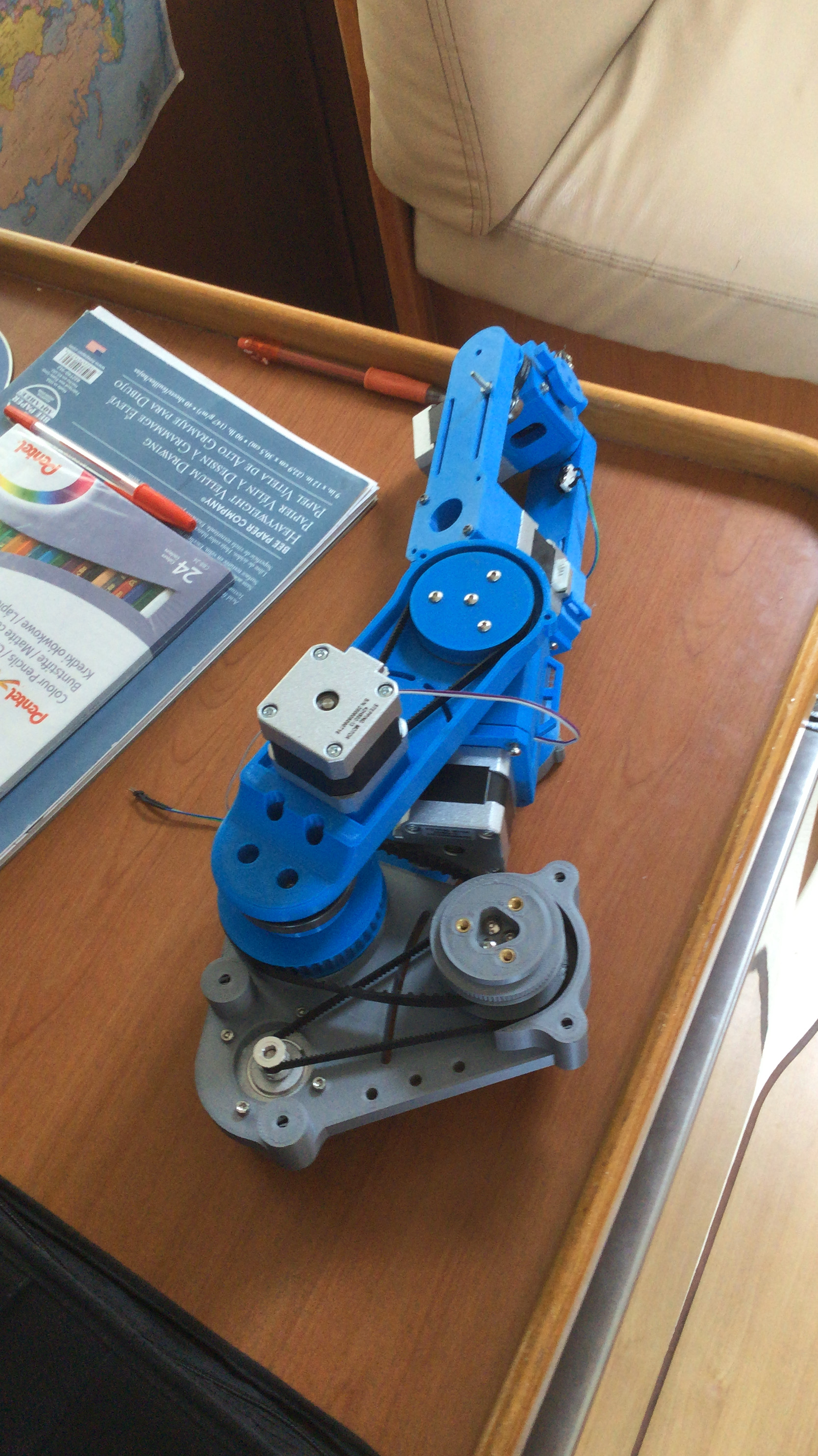
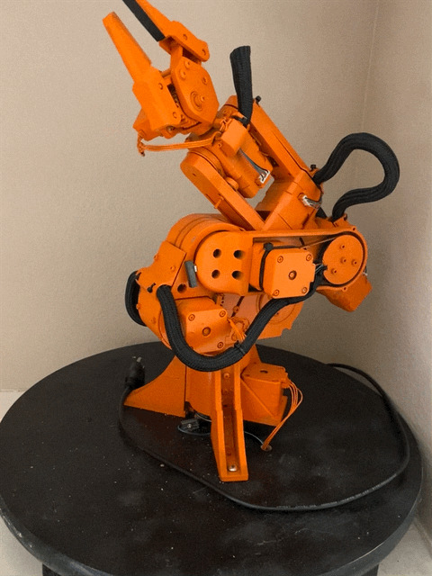
I started this project so that I could capture the interest of future employers. While living on the boat, parts were scarce. The first thing I did was order all the parts I could need because shipping can take months. I found everything for under $200 because my budget was low. It took multiple tries to finally get a practical design. I found out that you need to design a robot arm from the tip of the robot down to the base to ensure that there is enough torque for each axis. Belts were used for the gear reduction because other drives are much more expensive. The motors were all NEMA 17 stepper motors, and the whole structure was 3D-printed.
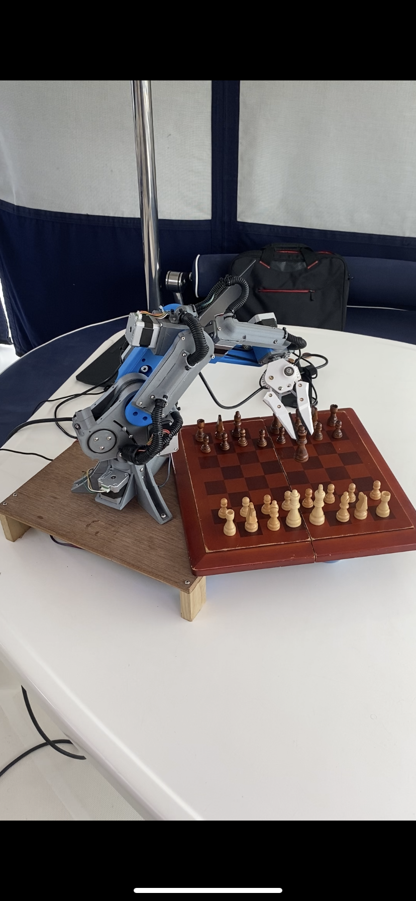
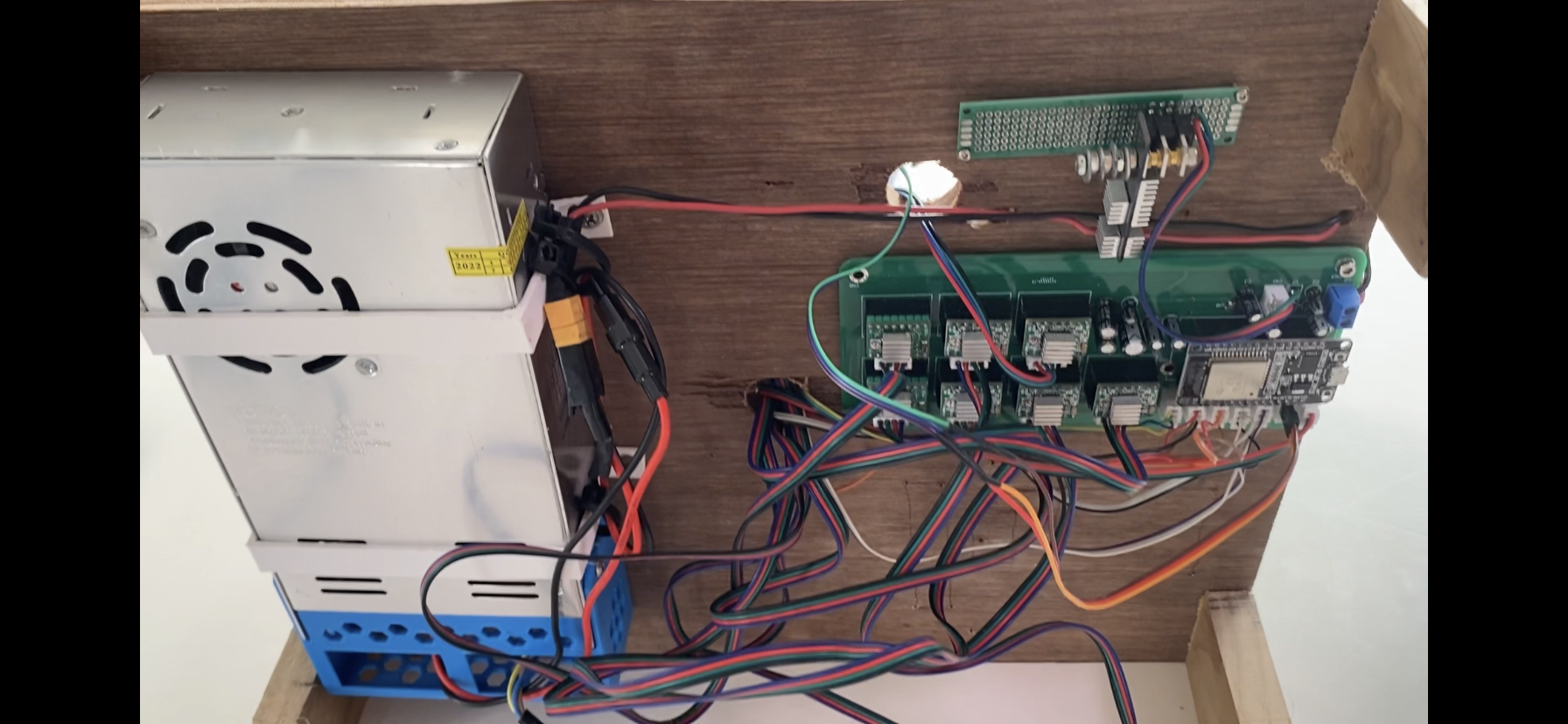
I started building and 3D-printing the robot as I designed it. After the first two axises were built, I was already testing it and making it move. I used a raspberry-pi and a circuit board that I made to control it (as you can see in the video above). Eventually the robot started taking shape. Once build, the wiring was getting in the way of the joints so I routed the wires more professionally. I also built a wooden base with the spare scraps of wood we had on the boat. Finally, I put all of the electronics on the bottom side of the wooden base to keep them out of the way.
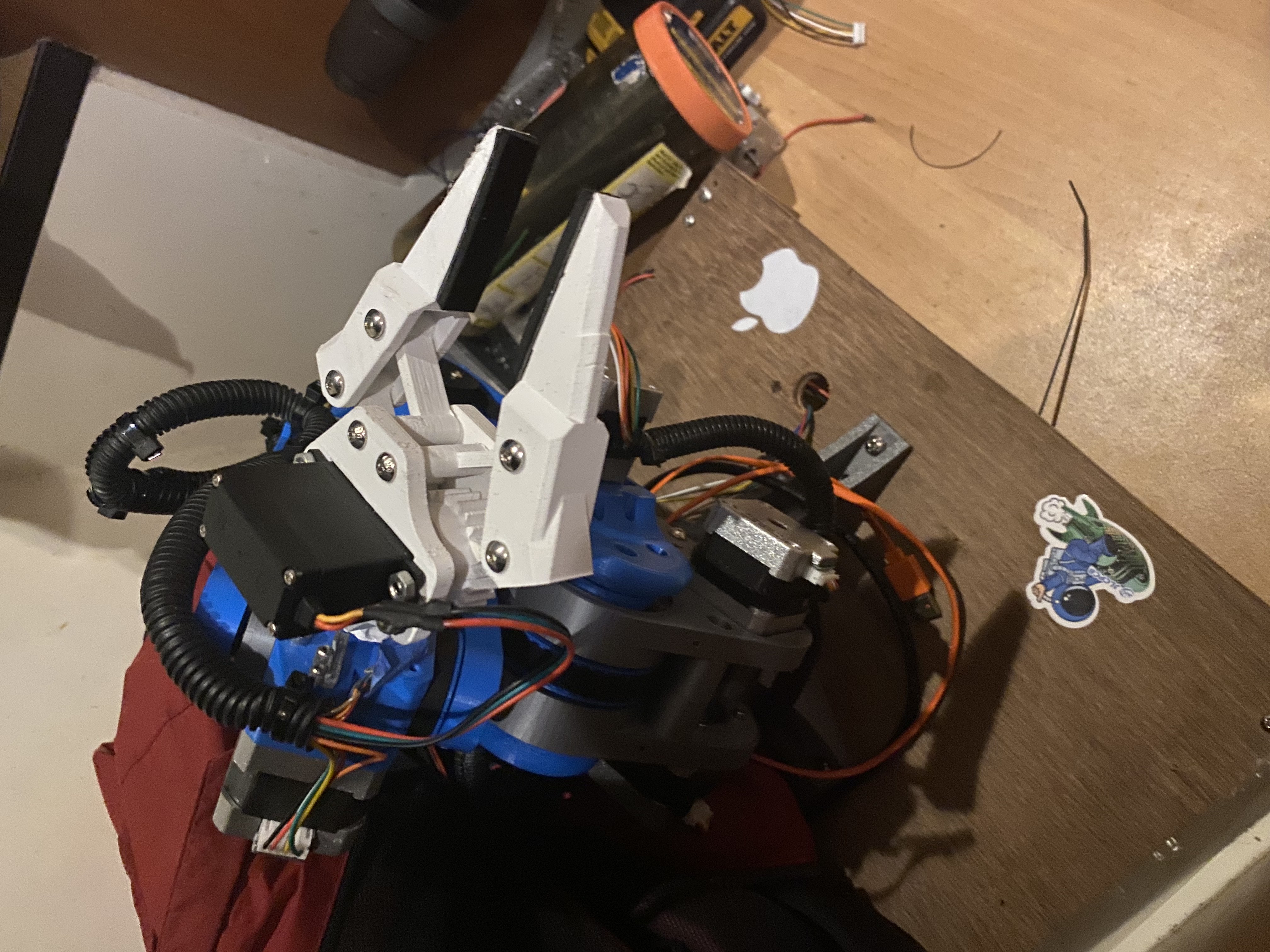
When my family sailed from Fiji to Vanuatu, I wrote a program to simulate the robot arm and control the robot arm over WiFi. The program had a window where a 3d view of the arm was rendered. It also had a ton of controls to move each joint and open the claw. I had to figure out a lot of things like homing, WiFi communication, and stepper motor velocities which was tedious. Finally the whole robot was working. I could successfully pick up small things with simple movements but complex movements were difficult without inverse kinematics. I did a lot of research on inverse kinematics and decided to try and make my own analytical kinematic model. It was harder than I thought but after using some matrices and trigonometry, it worked perfectly. The movements were jerky so I found a way to add acceleration to each movement. Another problem was that the limit switches were bulky and limiting the range of motion so I switched to hall effect sensors with magnets on each joint. I also was sick of making robot programs with my software over and over so I made a file system for the robot programs.
The robot ended up being a cool project but there was a lot of problems. I was satisfied with the achievements of this robot because I wanted to move on to a new one in attempt to try and resolve all of the issues of this one. Robot arm MK2 began.
Here is a collection of videos and photos of the project!
This is a video of the robot working durring the early stages of it's existance.
This is a video of the robot working durring the latter stages of it's existance.
This is the new base I made for the robot.
This is the robot playing chess.
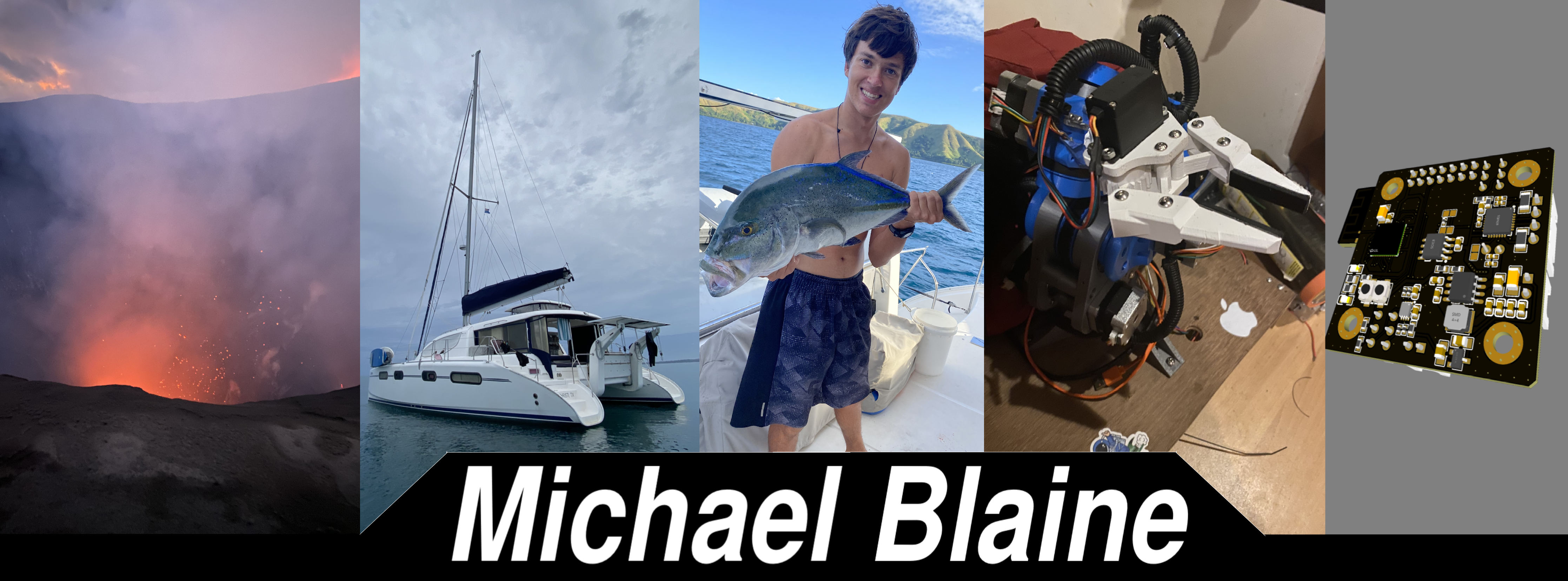
These are the electronics including the custom PCB I designed.